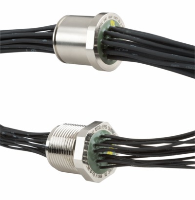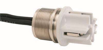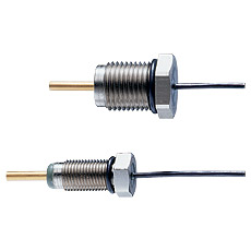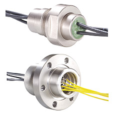
Bushing explosion-proof and pressure-sealed
Benefits
- High pressure stability
- High temperature resistance
Marking
ATEX:
Ex II 1/2 G Ex db + eb / db IIC Ga/Gb
Ex II 2 G Ex db IIC Gb
Ex II 2 G Ex eb IIC Gb
Ex II 2 G Ex db eb IIC Gb
Ex II -/2 G Ex db eb IIC Gb
Ex II -/2 G Ex eb IIC Gb
Ex I M 1 Ex db eb I Ma
IECEx:
Ex db + eb / db IIC Ga/Gb
Ex db IIC Gb
Ex eb IIC Gb
Ex db eb IIC Gb
Ex db eb I Ma
Ex-marking depend on selected configuration
Ambient Temperature
Temperature at rated operation:-55 °C ≤ Ta ≤ +150 °C
(-67 °F ≤ Ta ≤ +302 °F) with potting
-55 °C ≤ Ta ≤ +200 °C
(-67 °F ≤ Ta ≤ +392 °F) without potting
depending on the lead used and type of sealing
Description
The 07-96..-.. type series II 1G line bushing serves as a gas diffusion-proof isolation element for zone 0 (1G/2G) while simultaneously providing an electric connection for leads:
- between flameproof enclosures
- between flameproof enclosures and enclosures with another approved type of protection Category II 2 G
- flameproof enclosures and protected installations Category II 3 G or
-in the safe area
The core piece of this gas diffusion-proof leadthrough is a metal plate in which the stud-type bushings are insulated with glass. The electrical connection on both sides of the lead-through can be set forth with metal duct bolts, cable wires or hose lines as required. This connecting area is, or can additionally be, cast with a poured resin. The connector studs, connecting wires or the hose line of the line bushing II 1G must be connected in enclosures which conform to a type of protection standardised according to DIN EN 60079-0. The lead-through is compliant with the pertinent DIN EN 60079-0, DIN EN 60079-1 and DIN EN 60079-7 and DIN EN 60079-26 standards.
Technical Data
| Protection class | IEC 60529/EN 60529 Dependence on the design |
|---|---|
| Material | Sleeve: metal Insulator: glass Pour: EP resin, PU resin Bushing bolt: FeNi alloy steel, Niro steel |
| Pressure | -500 mbar to +400 bar depending on the design |
| Installation | Diameter flansch: Ø 10 mm to 250 mm Thread size: M10 x 1 to M72 x 2 |
| Voltage | ≤ AC 50 V/DC 75 V, 250 V, 690 V, 1 000 V |
| Current | up to 500 A |
| Connection | Core wires: 0.25 mm² to 16 mm² Threaded bolts: M3 to M30 (max. quantity of connections: 99) |
